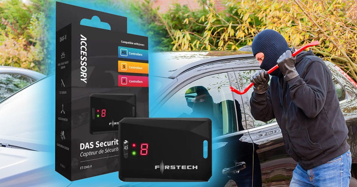
A laptop bag in the back seat, a smartphone in the center console or shopping bags in the rear of an SUV – each is the perfect temptation for a thief. In seconds, items you’ve spent your hard-earned money to acquire are gone forever. Protecting your vehicle with a premium car alarm that includes the Firstech FT-DAS II security sensor is one of the best options for stopping theft, vandalism or damage.
This impressive device includes four security sensors in one compact, reliable package. The FT-DAS II is also a key component in why Compustar or Arctic Start remote car starters are the safest solutions for vehicles with manual transmissions. Let’s take a look at the FT-DAS II in detail.
Firstech FT-DAS II Features
The FT-DAS II uses a high-sensitivity, multi-axis digital motion accelerometer to detect attempts to break into your vehicle or damage from shopping carts or another vehicle. If the device detects a moderate impact, the system chirps the siren a few times to scare off thieves or alert another driver that they may have touched your vehicle. If the impact is significant, the full alarm will sound instantly. The impact sensor is excellent protection against someone using a battery-powered reciprocating saw to try to steal a catalytic converter or using a cordless impact gun to steal your wheels. Your Firstech dealer (Compustar or Arctic Start) can fine-tune the sensitivity of the impact sensor to keep your vehicle safe without having false alarms when it’s windy or noisy.
The FT-DAS II includes programming logic that monitors the accelerometer to detect when the vehicle is being lifted. If someone is trying to steal your wheels or the car is being hoisted onto a flatbed or raised by a tow truck, the tilt-detection feature will trigger the alarm.
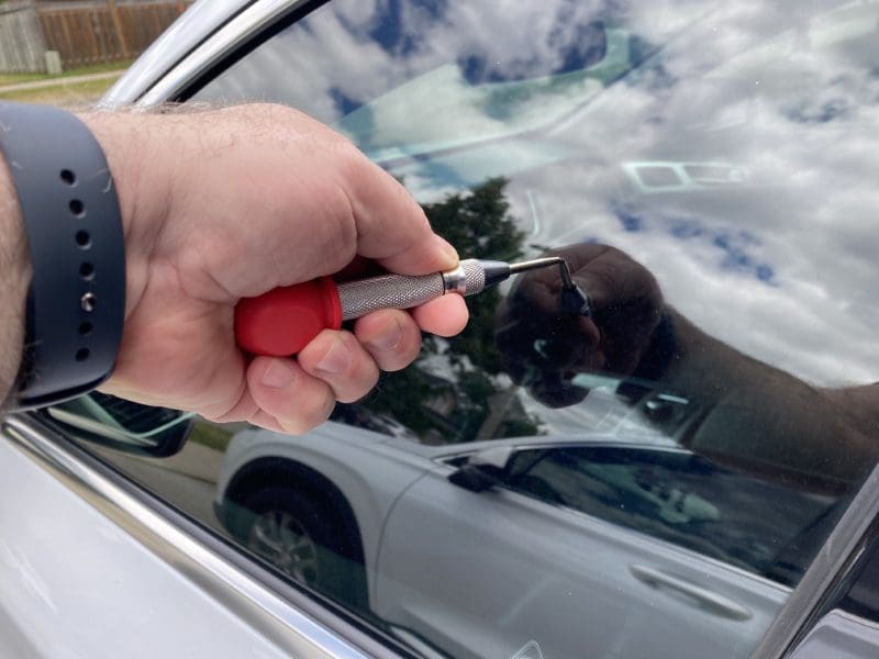
The most obvious difference between the original FT-DAS and the FT-DAS II is the inclusion of glass-breakage detection. If a thief uses a hammer or punch to break a window, the microphone will detect the sound of the glass shattering and trigger the alarm.
Forward-Motion Detection Delivers Class-Leading Remote Start Safety
The FT-DAS II is required anytime a CM7 or CMX control module is installed as a remote car starter on a vehicle with a manual transmission. The forward motion sensor is active during the remote start process and will shut the engine down immediately if it detects the car or truck moving forward. Even if all the safety systems have been bypassed (which is very difficult to do), you can be confident that your vehicle won’t drive through your garage when you activate the remote starter. No other brand of manual-transmission-compatible remote starter offers this level of safety and security.
Get Security Alerts Remotely
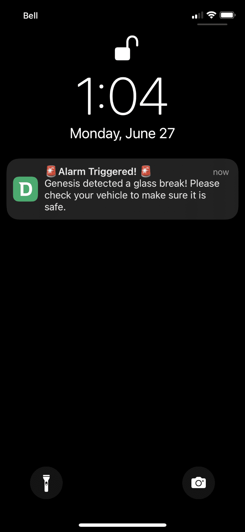
If your remote starter or security system is equipped with a two-way remote like the T13, R5, T12, T11, Q9, 901 or the T9, you’ll get alarm alerts as long as you’re within range of your vehicle. The remote will beep and, depending on the model, tell you which security zone was triggered. The security alerts include warnings for the door, hood and truck triggers and those from the FT-DAS II. For ultimate protection, the DroneMobile telematics system will show alarm alerts as notifications on your smartphone no matter where you are, as long as your phone has access to the internet.
Factory-Installed Security Systems Don’t Offer Damage Protection
You may have been told that your vehicle came from the factory with a security system. In most automobiles, these systems are typically just a transponder key that helps prevent vehicle theft. They do nothing to protect you against smash-and-grab intrusions as they don’t include an impact or shock sensor. A dedicated Compustar or Arctic Start system that includes the FT-DAS II will provide an instant alert if someone is attempting to damage or break into your car, truck or SUV.
Protect Your Vehicle with A Premium Digital Security Sensor
Whether you’re worried about theft, damage in a parking lot or vandalism, a security system or remote car starter that includes the Firstech FT-DAS II is the best protection you can buy. Drop by an authorized Compustar or Arctic Start dealer to ask about a vehicle protection system today. You can learn more about Compustar remote starter and security solutions by visiting their website and following them on Facebook, Instagram and YouTube.
This article is written and produced by the team at www.BestCarAudio.com. Reproduction or use of any kind is prohibited without the express written permission of 1sixty8 media.