 Not all that long ago, upgrading the performance of your car audio system required that you replace the factory source unit. The industry had dozens of premium CD receivers with state-of-the-art signal processing and high-end digital-to-analog converters. The popularity of these source units and the audio systems that could be built around them was not lost on automakers.
Slowly, technologies like Bluetooth audio streaming and hands-free calling, USB support for digital audio files, and direct smartphone control have become the norm when you purchase a new vehicle. On the audio side of things, automakers have partnered with companies like Panasonic, Bose and Harman to provide expertise in configuration and tuning to elevate the performance of factory-installed systems dramatically.
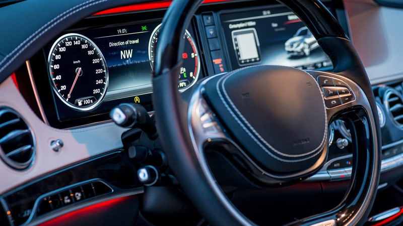
If you go shopping for a new vehicle, you may notice that the radio is no longer a single component in the vehicle. Some manufacturers spread audio control and information display across three locations in the vehicle. Replacing the radio simply isn’t an option in many applications.
For those of us who want to upgrade our sound systems, the philosophy and process have changed a great deal. If we can’t replace the radio, can we get great sound? Thanks to ongoing research and innovation, the answer to that question is a resounding “yes.” Let’s look at how this is accomplished.
Fix What’s Broken

The source unit in a modern vehicle usually has most of the features and functionality we need. Smartphone integration solutions like Android Auto and Apple CarPlay, well-tuned Bluetooth hands-free, and a backup camera are very common. Where most audio systems suffer is in the amount of power they have available and the speakers.
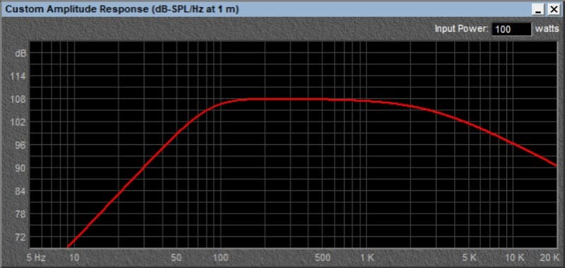
Not having enough power means that when you turn the volume up past a certain point, the signal begins to distort. Not only does this sound bad, but it delivers additional energy to the speakers and can damage them. It has been said that you can never have too much power. In terms of ensuring the signal going to the speaker is clean and undistorted, this statement is perfectly true.
The second issue is the speakers that automakers use. Even in premium branded systems with names like Lexicon, Bose, Boston Acoustics or JBL, the speakers are, at best, mediocre. Sure, there are some exceptions, but on average, they lack the accuracy, detail, excursion capabilities and power handling of a quality aftermarket speaker.
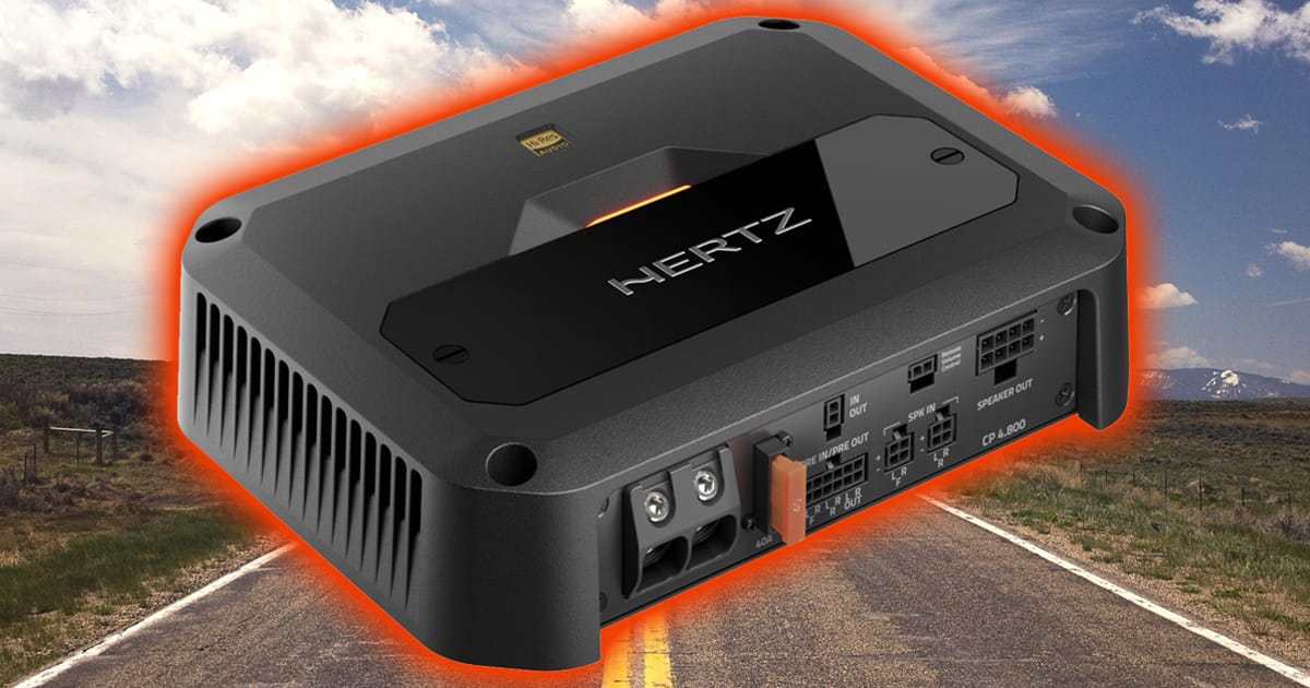
If you want to improve the performance of your factory sound system, add more power and have better speakers installed. The recipe is really just that simple.
The Steps to Success
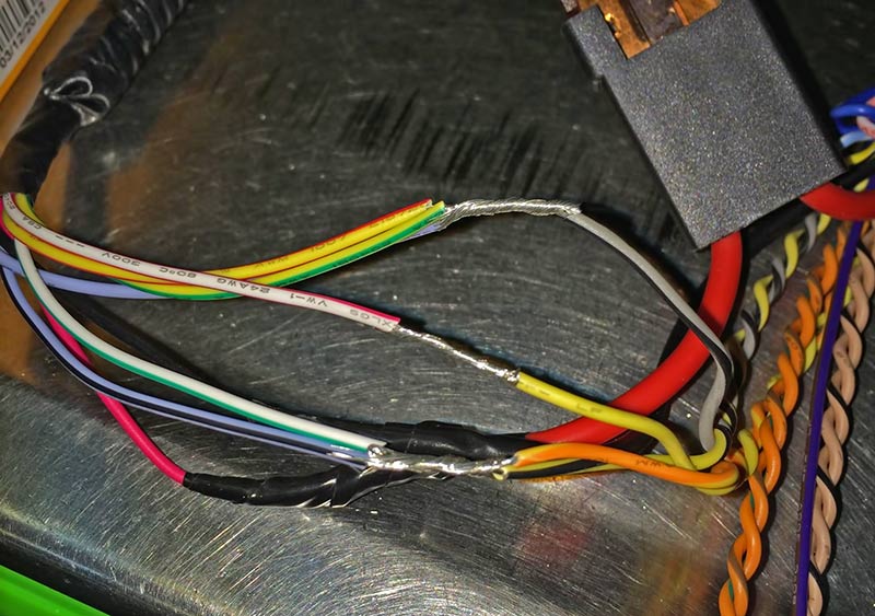
The first step your local mobile electronics retailer will take is to determine how best to integrate with the factory radio. In some cases, this is as simple as connecting the speaker wires from the back of the radio to speaker-level inputs on a new amplifier. If the factory stereo system includes an amplifier, then a line level converter may be required to reduce the voltage to something that the new amp can use properly.
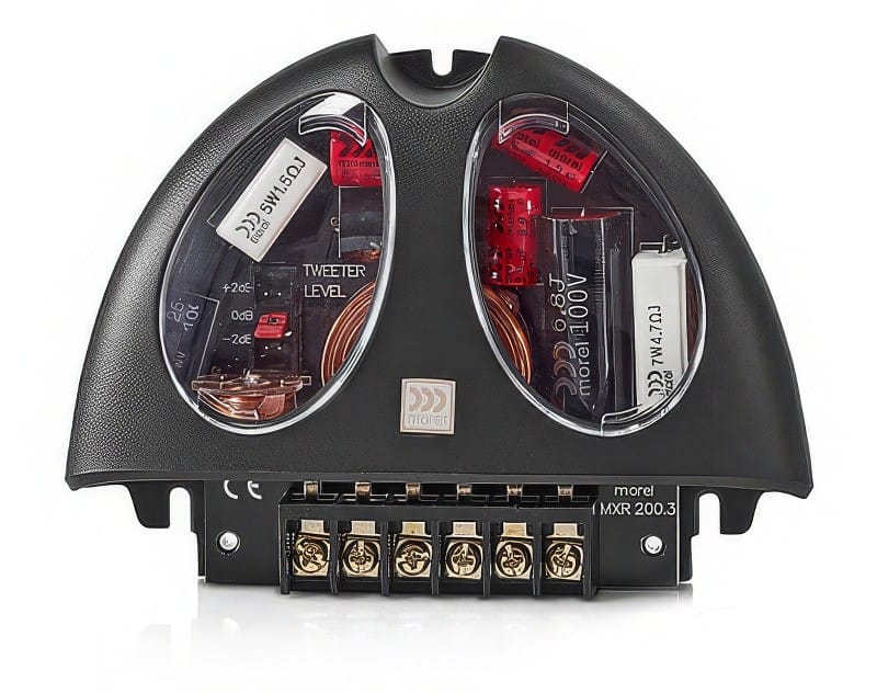
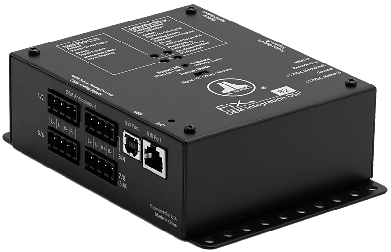
If you have a more-advanced factory audio system that includes equalization, crossovers and signal delay, the integration process requires hardware between the factory amp and your new high-power amplifier. Several companies have developed processors that will undo much of the tuning built into these amps and provide a full-bandwidth signal that your installer can use to build the new system.
Another option is to use a factory amplifier replacement module. These devices accept the audio signal from the radio and, in most cases, capture volume control information from the vehicle’s CAN bus. The output of these replacement modules works just like an aftermarket radio – we have a full-bandwidth signal that can be used to drive new amplifiers.
Advanced System Integration
At the highest levels of factory audio system integration are systems that include upmixers. An upmixer is a device that takes the stereo audio signal from your radio, iPhone or CD and converts it to multiple channels. In most cases, this includes left, center, right, left rear, right rear and subwoofer signals. Why do automakers implement upmixers? When tuned properly, your music will sound great from every seat in the vehicle. Both the driver and passenger will hear a performer recorded at the center of the stage from the middle of the dash.
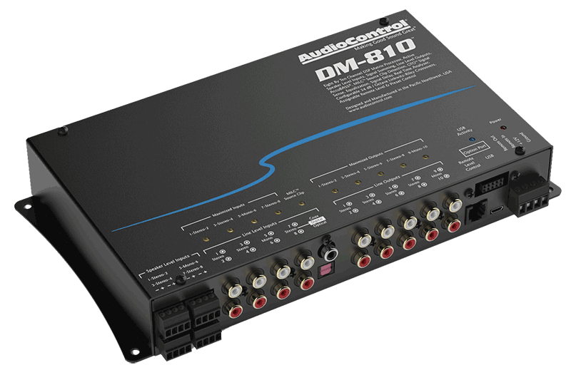
To integrate with these systems, it’s often best if we keep the factory signal processing in place, then add a digital signal processor (DSP) between the factory amp and the new high-power amplifiers. The DSP lets us fine-tune the frequency response of the system so the new speakers can produce an amazingly accurate and lifelike listening experience.
Speaker Upgrades

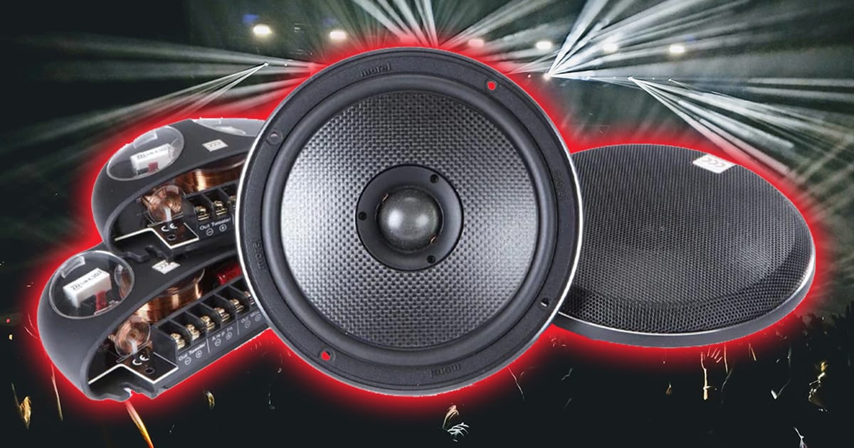
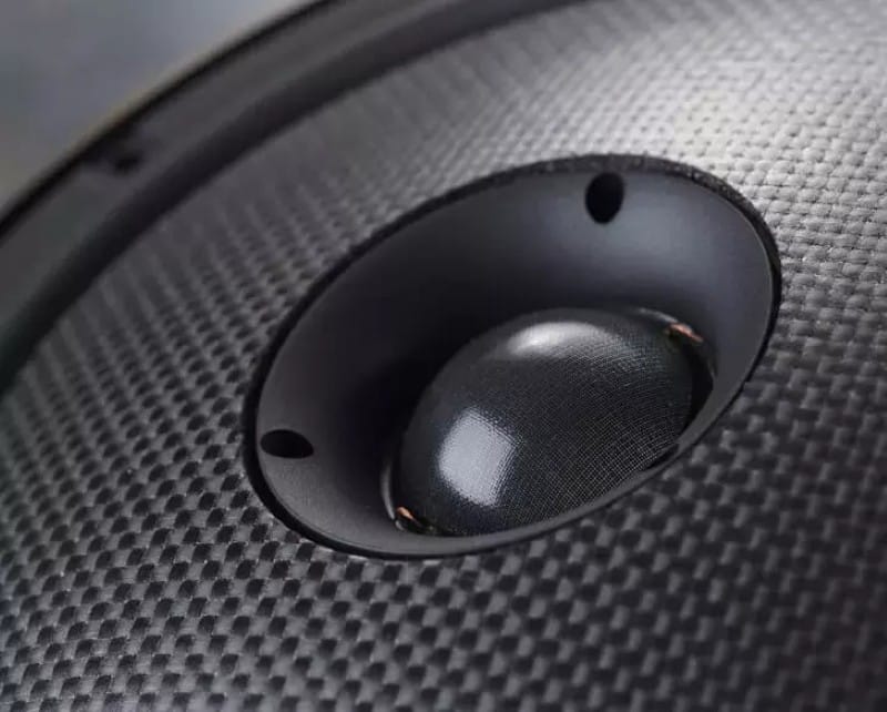
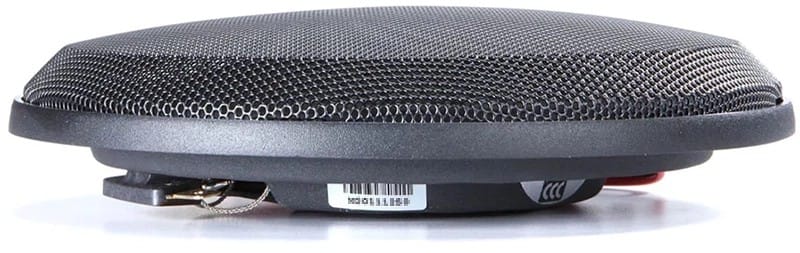
As we mentioned, it is important to upgrade the speakers in your vehicle to achieve an overall improvement in sound quality. Premium speakers provide smoother frequency response, extended bandwidth (they play lower and higher in the frequency spectrum), increased power handling and louder volume. If you are going to add amplifiers, then it only makes sense to ensure your speakers will be able to make use of that newfound power.
Speaker shopping can be somewhat difficult. Listening to speakers on display boards doesn’t always provide a sense of what those speakers will sound like in the vehicle. A close look at the speaker design, research into the brand’s reputation and a thorough understanding of speaker technologies may prove to be a better way to shop.
One problem with this approach is marketing. No matter the quality of a new speaker, every manufacturer wants people to think that their products are the best. Filtering the genuine features from the marketing fluff can be difficult. Work with your retailer to find a solution that sounds great, fits your budget and works with your application.
System Installation
If only installing mobile electronics equipment were as easy as setting up a new microwave. We can’t simply plug it in and turn it on. Wires have to be run, connections have to be made and equipment has to be mounted. Budget for these requirements before you go shopping. The performance of a new speaker in your vehicle depends as much as on how it is installed as on its design.
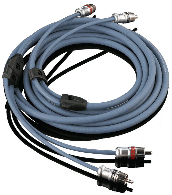
If you are changing speaker sizes, you will want plastic adapters instead of wood to eliminate the chance of damage due to water infiltration. You will want high-quality interconnects to ensure noise can’t creep into the system. You will need large-gauge power wire to deliver current to your new amplifiers efficiently. Talk to your retailer about the products and processes he uses.
It’s Not Over Yet
 The last step of the installation process is to tune the system. Even the addition of a subwoofer requires proper tuning. The installer should confirm that the output of the sub is combining acoustically with the rest of the speakers in the vehicle. The sensitivity of the amplifier should be set so the systems have excellent overall balance and won’t distort when the volume is turned up.
At the top end of the spectrum, systems with new DSP units require that each channel of the sound system be tuned to provide smooth frequency response. Having the right channel a little brighter or more laid back than the left will cause the location of a performer or an instrument to seem to move around the vehicle as its frequency content changes. We want everything to be stable and naturally balanced. Budget for at least an hour or two of tuning to ensure you are getting everything you can from your upgrade.
Enjoy Better Sound
Upgrading your sound system with new amplifiers and speakers is a great way to increase maximum volume, reduce distortion, and improve imaging and staging. The process most certainly doesn’t require a new source unit, but it does take some planning. Work with your local mobile electronics retailer to design an upgrade for your sound system. The experience will truly let you enjoy your music in a way you have never heard before.
This article is written and produced by the team at www.BestCarAudio.com. Reproduction or use of any kind is prohibited without the express written permission of 1sixty8 media.