 Years ago, when someone wanted to make their car stereo system sound better, they bought a new radio. With the complexity of modern infotainment systems, upgrading your radio isn’t always possible. So, what’s a music enthusiast to do? As it turns out, the radio is the least of your worries – unless, of course, it happens to be broken. Read on to find out more about our tried-and-true OEM audio upgrade path.
The Weakest Link
What is it about factory stereos that enthusiasts don’t like? Ask most of them, and they’ll tell you that the system doesn’t play loudly enough and that it doesn’t produce enough bass. Rather than muck around with expensive source units and complicated integration modules, why not simply address the weak points?
Step 1: Add a Subwoofer
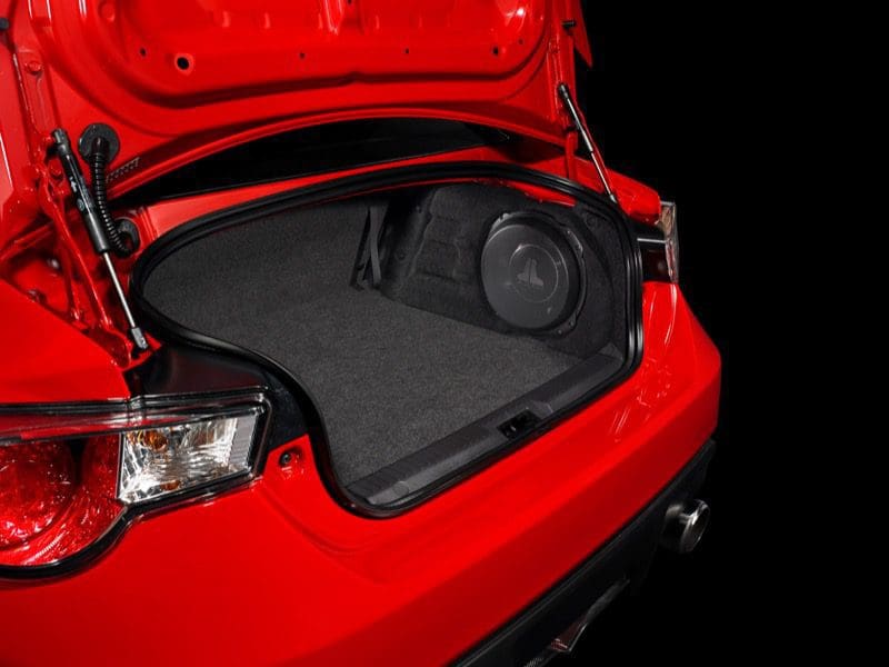
Subwoofers get a bad rap. The stereotype is that they are very large and are only good for making mirrors shake and the trunk lid vibrate. The reality is that a subwoofer is a fundamental component of a truly great-sounding audio system upgrade. Even in a Mustang or Corvette with 8- or 10-inch door speakers, adding a properly designed subwoofer system will result in a massive improvement.
Before you get hung up on losing your storage space to a subwoofer system, there are many options for extremely compact solutions that take up little to no room at all. Several companies offer compact powered woofers that will fit under a seat. These solutions can warm up your sound system nicely.
The next step up in performance would be an enclosure that places a sub in an existing storage area. Many companies offer vehicle-specific solutions that use fiberglass or roto-molded plastic enclosures. Some of these solutions include an amplifier and vehicle-specific wiring that makes the installation quick and easy. These systems typically feature an eight- or 10-inch subwoofer. The result is solid low-frequency extension and great output up to moderately loud listening levels.
If you are searching for the epitome of subwoofer performance, your local mobile enhancement retailer can create an enclosure that is specific to your vehicle and your requirements. From an audiophile-grade single sub in a compact sealed enclosure to something with two or more high-excursion drivers in a large vented cabinet – your choice depends on your expectations. Listen to a few systems and decide what’s right for you.
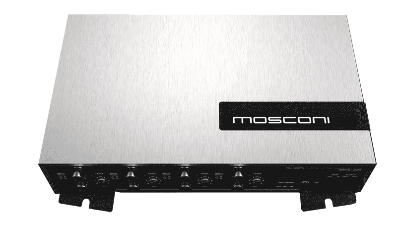
Step 2: Add an Amplifier
We’ve addressed the bottom few octaves of our system with the subwoofer. The next step is to add an amplifier to the midrange and high-frequency speakers. If your factory stereo doesn’t have an amplifier, then you are likely only getting 18 to 20 watts of real power to each speaker. Even a modestly powered amplifier will provide about three times as much power. With more power, your stereo will sound better at higher volumes. The garbled distortion that plagues most factory stereo systems when you turn up the volume will be gone.
Because most amplifiers include an electronic crossover, your installer can filter out the bass from your smaller speakers. This filtering allows your small speakers to do a much better job of reproducing midrange and high frequencies – both clearer and louder.
I’d Like to Order the Combo, Please
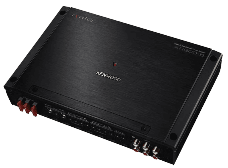
If you know your ultimate goal for your sound system will include a subwoofer and an amplifier for the speakers, you may want to consider buying a five-channel amplifier. These amplifiers include four discrete channels for your front and rear speakers and a high-power channel dedicated to powering a subwoofer. By combining your amplification requirements into a single chassis, your installer will be able to install it faster, and you won’t need any power distribution components.
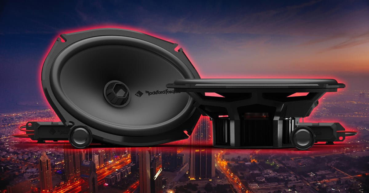
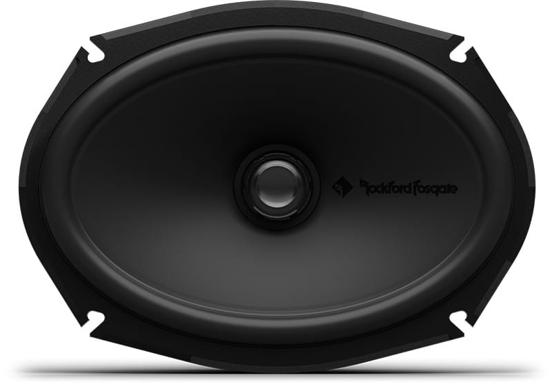
Step 3: Upgrade Your Speakers
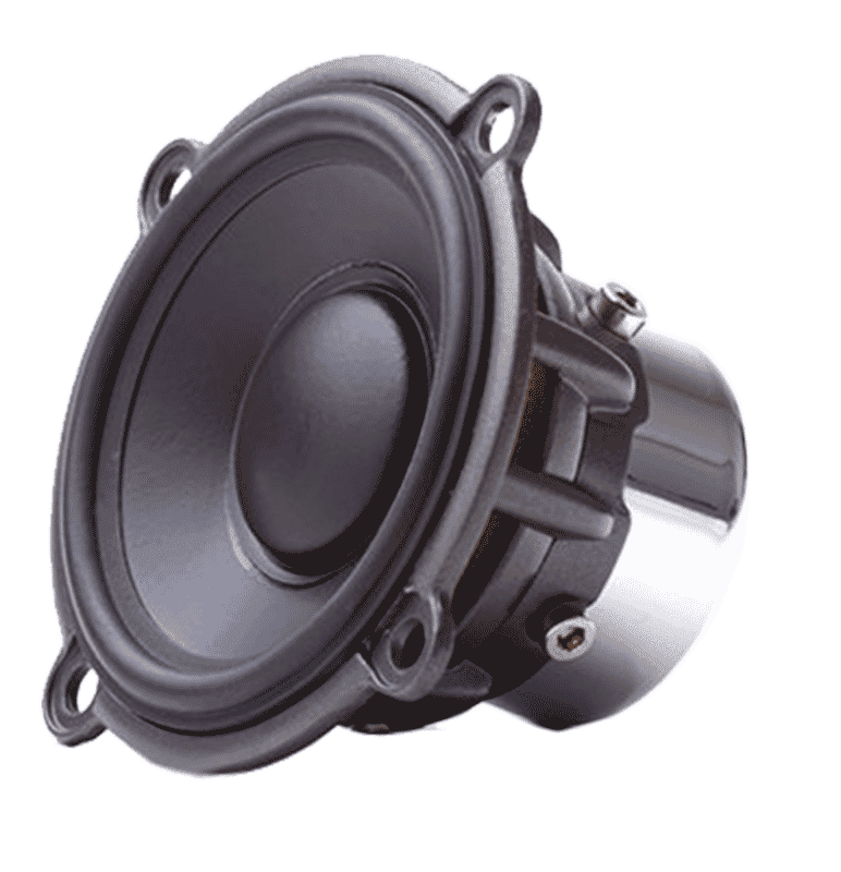
Once you have an amplifier, it’s time to upgrade your speakers. Though there are arguments for a speaker upgrade as an early part of the process, speakers need amplifier power to shine. Connecting a set of components to the little amplifier built into a radio simply doesn’t do them justice.
Premium aftermarket speakers not only provide smoother frequency response and less distortion than OEM speakers, but their increased excursion capabilities will allow them to play louder – but only when they have adequate power.
Choosing a set of speakers can be very difficult. There are thousands of options available from hundreds of manufacturers. Most retailers carry one or two high-end brands, each with a variety of options in each speaker size. While it is often easier to buy well-known brands, many companies put more effort into marketing than they do into developing speakers that sound amazing. We suggest auditioning as many speakers as possible, using the same selection of music each time. After a while, it’ll be easy to hear the difference between a great speaker and one that is marketed well.
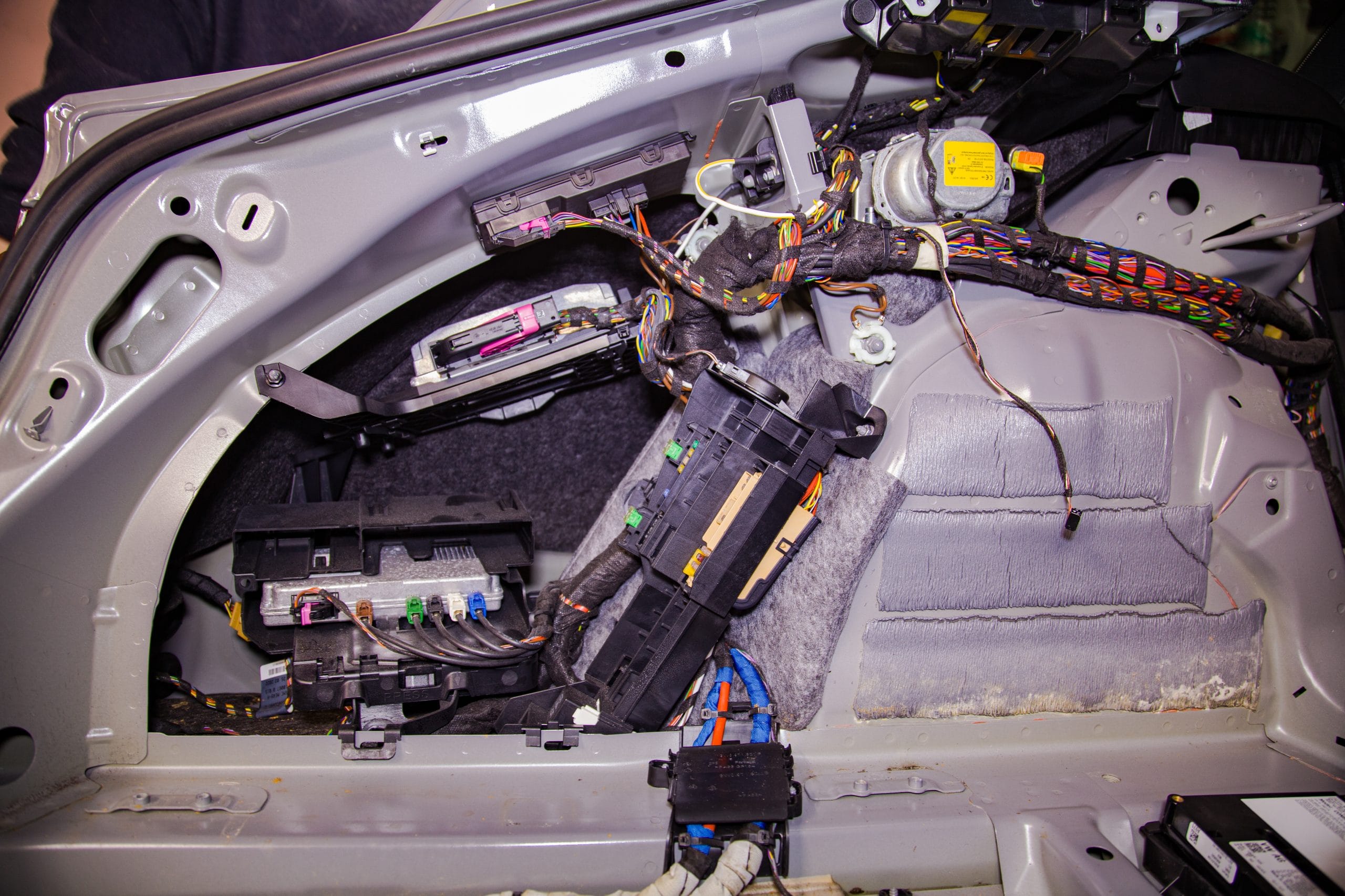
Installation Matters
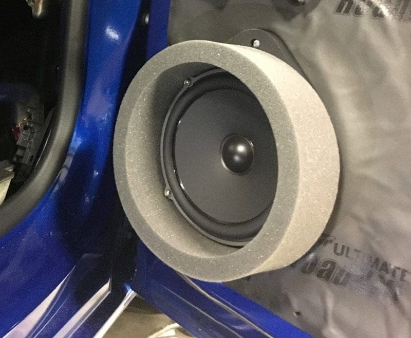
Unlike a new Bluetooth speaker from the local big box store, the performance of your mobile sound system depends significantly on its installation and configuration. Amplifiers require properly sized high-quality wiring. Electrical connections need to be mechanically secure and properly protected. Speaker installation has a dramatic effect on their performance. Solid mounting adapters that are water-resistant are an absolute must. The option to add sound damping material to the doors or foam coupling rings to the front of the speakers is also a sign that the shop you are dealing with cares about the performance of your system.
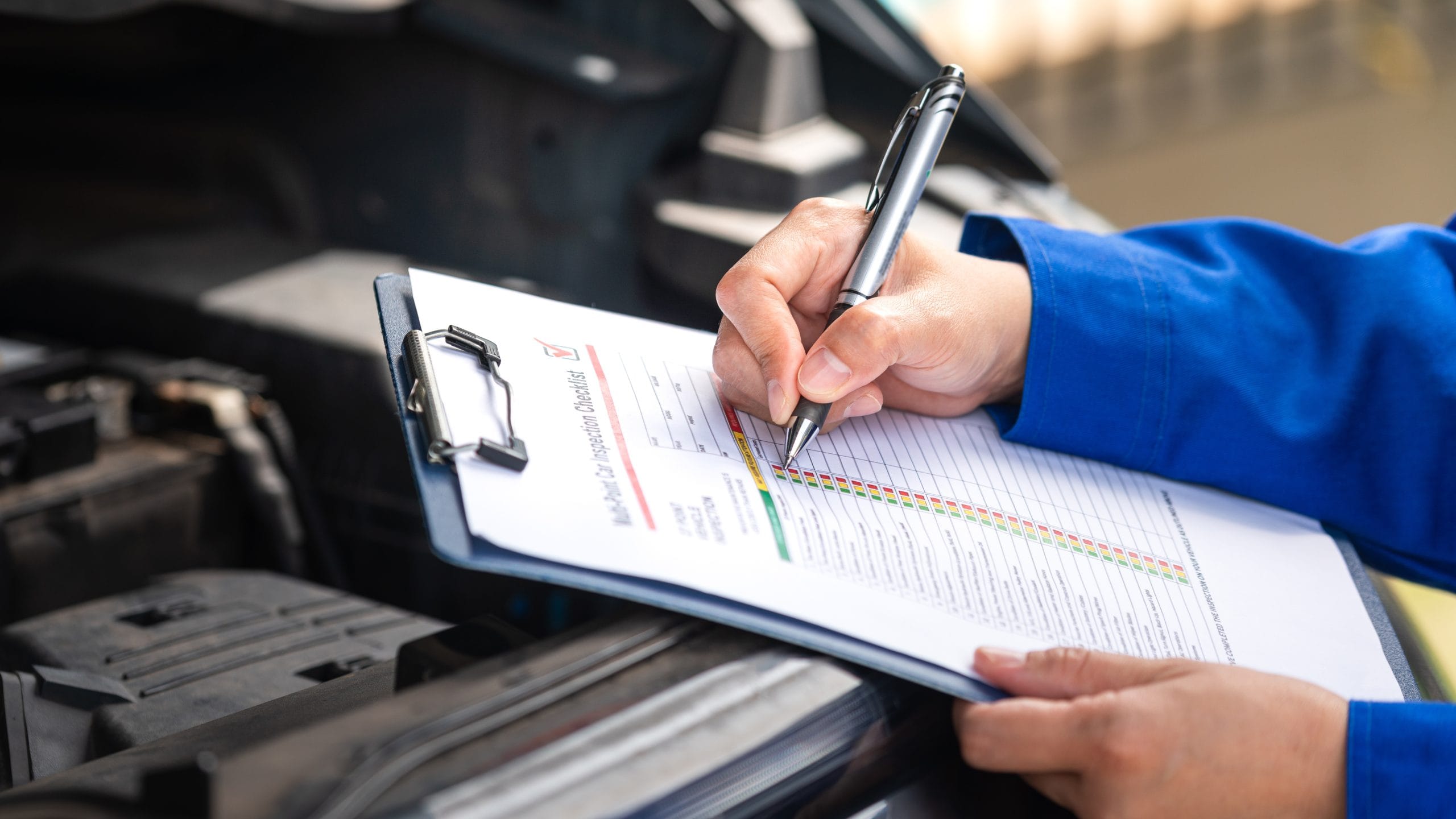
Amplifiers need proper configuration. Each source has different voltage capabilities. These voltage capabilities determine how the sensitivity controls on your installer will configure your amplifier, and ultimately, how loud the system will play without significant distortion. Crossovers need to be set properly to protect small speakers from damage while still ensuring your system sounds great. Many technicians make the process look easy, but it takes years to learn the art of proficient system configuration.
The Next Steps
Though we’ll save it for a future article, the next step in upgrading your OEM stereo system would be to add a digital signal processor. A properly tuned processor will allow your installer to compensate for speaker placement and reflections and resonances within the vehicle. The result is smooth and natural frequency response and a dramatically improved soundstage with impressive imaging.
Upgrade Your OEM Stereo System Today
If you are tired of distorted sound and wimpy bass, drop by your local mobile enhancement retailer and ask about upgrading your sound system. With a carefully planned upgrade path, you can work towards whatever goal suits your requirements in stages. Each stage will provide an audible and impressive upgrade. With each step, your music will sound more lifelike and realistic. It will truly be a case of having heard your favorite songs for the first time, all over again.
This article is written and produced by the team at www.BestCarAudio.com. Reproduction or use of any kind is prohibited without the express written permission of 1sixty8 media.