Would you think it was possible to pack a whole slew of technologies into a pair of car audio speakers? For the fanatics at Rockford Fosgate, that tech translates to more output and better sound in your vehicle. In this product spotlight, we’ll take a deep dive into the Punch Series P1650 6.5-inch and the P1694 6×9-inch sets.
Rockford Fosgate P1650 Speakers
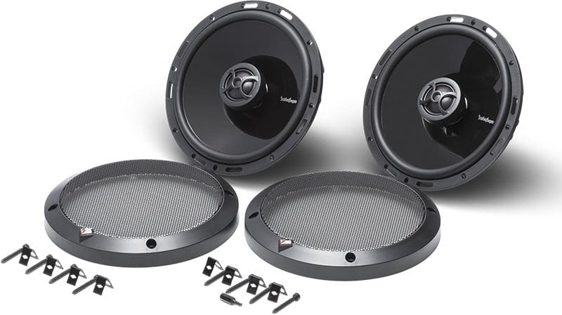
Perhaps the most popular speaker size today is the 6.5-inch coaxial. This size fits into hundreds of models of cars and trucks. The Punch Series P1650 set includes a pair of coaxial speakers that feature mineral-filled, injection-molded polypropylene woofer cones and ¾-inch treated PEI dome tweeters. The addition of minerals like mica helps damp resonances to reduce distortion while improving the thermal stability of the cones.
The cone is attached to the basket with a Santoprene rubber surround that will outlast conventional foam designs. The P1650 drivers use the Vertical Attach Surround Method (VAST) to increase the effective radiating area of the driver for more efficiency and bass output. To ensure smooth frequency response, the P1650 set uses -12 dB/octave crossovers concealed within the basket. Rockford Fosgate calls this its Integrated Concealed Crossover (ICC) design. In addition to being neat and tidy, there are no extra modules (external crossover enclosures) for your installer to deal with, so the installation will be quick and efficient.
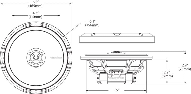
Choosing speakers that fit your vehicle is as important as selecting ones that sound great. The P1650 speakers feature the FlexFit2 stamped basket design. This design provides eight mounting holes and eight elongated slots to ensure that the speaker can fit a variety of vehicle OEM mounting points. The mounting depth is specified at 2.24 inches. A set of steel mesh grilles is also included.
Wrapping up the specs on these drivers, we have a continuous power handling rating of 55 watts and a max rating of 110 watts. Their nominal impedance is 4 ohms, and they have a sensitivity rating of 88 dB SPL at 1 watt at 1 meter. Sensitivity at this level typically indicates that the suspension design is optimized for sound quality.
Rockford Fosgate P1694
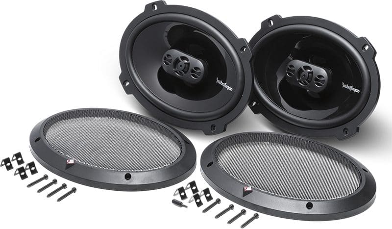
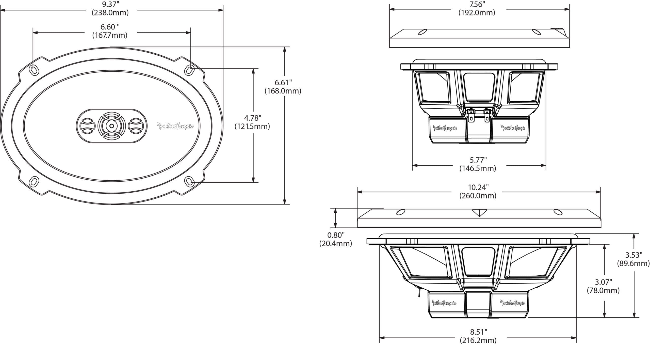
If you have a car or truck with 6×9 speaker locations in the doors or rear parcel shelf and you want to rock out, the four-way P1694 6×9 set is the perfect option. Once again, these speakers include the same mineral-doped polypropylene woofer material as their little brothers and use the VAST surround design for optimized efficiency. These drivers feature a pair of PEI dome tweeters that flank a compact titanium composite cone midrange driver that also includes a rubber surround.
The mounting depth on the P1694 speakers is 3.07 inches, and the drivers include steel mesh grilles and mounting hardware. They can handle 75 watts of power continuously and peaks of 150 watts. Their nominal impedance is 4 ohms, and they have an impressive 91 dB SPL 1W/1M efficiency rating.
It’s worth noting that all of Rockford Fosgate’s speaker and subwoofer specifications fully comply with the CTA-2031 standard for the Testing and Measurement of Mobile Loudspeaker Systems. What does this mean? The dimensions are accurate, and the specifications are entirely believable and uninflated. Not all car audio brands can make this statement.
Upgrade Your Vehicle with Rockford Fosgate Punch Speakers
If your car, truck or SUV needs new speakers, drop by your local authorized Rockford Fosgate retailer and ask to audition the Punch Series P1650 and P1694. We’re confident that you’ll be impressed by what you hear. For more information on Rockford Fosgate audio upgrades for cars, boats, motorcycles and powersport applications, visit their website. You can learn about new product releases by following them on Facebook, Instagram and most definitely on YouTube.
This article is written and produced by the team at www.BestCarAudio.com. Reproduction or use of any kind is prohibited without the express written permission of 1sixty8 media.